I want to make a host that enter/connect to my LAN either via switch or via access-point take/receive automatically proper IP address without I must configure it. How can I do that?
Monday, 23 November 2015
Frame Relay
I want to connect my store branch to my headquarter via Frame Relay network. How can I configure my router?
HSRP
I want host to switch to another router as their gateway without I manually change their gateway address. How can I configure all of my internal/local routers to support this requirement?
On each router, go to their inside-interface's configuration mode, do and type these:
1. Add virtual IP address.
Usually virtual IP address is the first usable IP address from the IP address segment. So like this:
R1(config)#int f0/0
R1(config-if)# standby ip 192.168.1.1
2. Set which router be the preempt
3. Set the priority
Virtual mac-address is will be used as L2 address of L3 virtual interfaces.
Where did this virtual mac-address came from?
At first, I think both routers will do some kind of negotiation upon their will be used virtual mac-address. But it is not. The virtual mac-address is decided/derived by each router directly, via configuring group number, group number 1 in this case, into their standby command. They don't need to negotiate the mac-address using sending and receiving packet.
So if you configure R1's with: standby 1 ip address 192.168.1.1, then it will directly derives its virtual mac-address as: and if you configure R2's with: standby 2 ip address 192.168.1.1, then it will directly derives its virtual mac-address as: .
Both router will start sending an ARP gratuitos packet (L2 packet that have source-address himself and destination-address himself also) and switch that connect to them will start record it inside its mac-address table. Like this:
On each router, go to their inside-interface's configuration mode, do and type these:
1. Add virtual IP address.
Usually virtual IP address is the first usable IP address from the IP address segment. So like this:
R1(config)#int f0/0
R1(config-if)# standby ip 192.168.1.1
2. Set which router be the preempt
3. Set the priority
Virtual mac-address
What is virtual mac-address?Virtual mac-address is will be used as L2 address of L3 virtual interfaces.
Where did this virtual mac-address came from?
At first, I think both routers will do some kind of negotiation upon their will be used virtual mac-address. But it is not. The virtual mac-address is decided/derived by each router directly, via configuring group number, group number 1 in this case, into their standby command. They don't need to negotiate the mac-address using sending and receiving packet.
So if you configure R1's with: standby 1 ip address 192.168.1.1, then it will directly derives its virtual mac-address as: and if you configure R2's with: standby 2 ip address 192.168.1.1, then it will directly derives its virtual mac-address as: .
Both router will start sending an ARP gratuitos packet (L2 packet that have source-address himself and destination-address himself also) and switch that connect to them will start record it inside its mac-address table. Like this:
NAT
Lets make user able to go to internet and our server able to be accessed via internet.
System of NAT consist of:
1. Access-list
2. Pool of public address
3.
Static NAT is always exist or always on. It doesn't need inside-user to go to internet first before it created inside border-router. So, outside-user can PING to inside-user anytime without requiring inside-user to PING that outside-user first.
Server is always uses static NAT not Dynamic NAT because Server is needed to be able to be accesses anytime without that server try PING to any outside-user first.
While, Dynamic NAT isn't always exist or always on. It requires inside-user to go to internet first before this type of NAT created inside border-router.
So, we need addtional knowledge to define which router's interface is inside and which interface is outside. This knowledge is important for both static NAT and dynamic NAT. Inside interface of NAT is usually
Outside interface of NAT usually interface that have public address.
Static NAT's command is begin with ip nat inside source static and so on. While Dynamic NAT's command is begin with ip nat inside source list and so on.
R2(config)#ip nat inside source static 192.168.20.254 209.165.202.131
Static NAT can also be used to do port forwarding. For instance: I want to change Web server port from 80 to 8080.
R2(config)#ip nat inside source static
Port forwarding static option (tcp and udp) available only in static NAT, like this:
R1(config)#ip nat inside source static ?
A.B.C.D Inside local IP address
esp IPSec-ESP (Tunnel mode) support
network Subnet translation
tcp Transmission Control Protocol
udp User Datagram Protocol
So, static NAT is without access-list. Dynamic NAT is with access-list.
Type of access-list that we used is just a standard named ACL. We use usually use named ACL not numbered ACL. Then we can reference this name from ....
And also this pool need a name.
System of NAT consist of:
1. Access-list
2. Pool of public address
3.
Static NAT is always exist or always on. It doesn't need inside-user to go to internet first before it created inside border-router. So, outside-user can PING to inside-user anytime without requiring inside-user to PING that outside-user first.
Server is always uses static NAT not Dynamic NAT because Server is needed to be able to be accesses anytime without that server try PING to any outside-user first.
While, Dynamic NAT isn't always exist or always on. It requires inside-user to go to internet first before this type of NAT created inside border-router.
So, we need addtional knowledge to define which router's interface is inside and which interface is outside. This knowledge is important for both static NAT and dynamic NAT. Inside interface of NAT is usually
Outside interface of NAT usually interface that have public address.
Static NAT's command is begin with ip nat inside source static and so on. While Dynamic NAT's command is begin with ip nat inside source list and so on.
Static NAT
All information that we need to configure static NAT are IP address private that Server belong and IP address public that we want the private IP address change/transfered/mapped .R2(config)#ip nat inside source static 192.168.20.254 209.165.202.131
Static NAT can also be used to do port forwarding. For instance: I want to change Web server port from 80 to 8080.
R2(config)#ip nat inside source static
Port forwarding static option (tcp and udp) available only in static NAT, like this:
R1(config)#ip nat inside source static ?
A.B.C.D Inside local IP address
esp IPSec-ESP (Tunnel mode) support
network Subnet translation
tcp Transmission Control Protocol
udp User Datagram Protocol
So, static NAT is without access-list. Dynamic NAT is with access-list.
Dynamic NAT
Dynamic NAT require a configuration of pool of public IP address, access-list and definition of outside-interface and inside-interface.Access-list
Dynamic NAT requires an access-list to determine/define which IP addresses allowed/permitted to be translated by NAT. IP addresses that outside or not included inside that list will not be translated, forever, hence IP addresses that are not listed in the access-list will unable to go to internet until they included in the access-list.Type of access-list that we used is just a standard named ACL. We use usually use named ACL not numbered ACL. Then we can reference this name from ....
Pool
To create pool we need to excludes public ip addresses that used for static NAT first but use mask that ISP give to customer/us a block of public ip address, like 255.255.255.252 if the ISP give us 4 public IP addresses to be used.And also this pool need a name.
Ubuntu
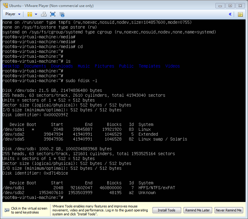
By default, storage devices that are plugged into the system mount automatically in the /media/<username> directory
1. Find the disk using comand lsblk
2. Find the name of the disk, in my case:
/sdb1
3. Create mounting point
1. Find the disk using comand lsblk
2. Find the name of the disk, in my case:
/sdb1
3. Create mounting point
sudo mkdir /media/external
Observing Hard Disk properties/parameters
So what are heads, sectors/track, cylinders, etc. of a Hard disk properties is all about?
Sector 0 of the disk is called the Master Boot Record (MBR). Within the MBR there is a field that identifies the format for each partition on the disk. For example NTFS is 07 (hexadecimal), FAT32 is 0B, Linux is 83, etc.
 |
| Picture 1 |
Sector 0 of the disk is called the Master Boot Record (MBR). Within the MBR there is a field that identifies the format for each partition on the disk. For example NTFS is 07 (hexadecimal), FAT32 is 0B, Linux is 83, etc.
Sunday, 22 November 2015
Don't reinvent the wheel what thats mean?
Dont reinvent the wheel means use the template code that available on the internet and written in various language.
Can we use table as to layout an html?
Can we use table as to layout an html?
Although we can achieve pretty nice layouts with HTML tables, but tables weren't really designed as a layout tool. Tables are more suited to presenting tabular data.
1. Inheritance
2.
And inside it we add texts/sentences:
Next, we add width property/paramater to parent-div and each child-div:
Next we add background color to each div, this time we use css:
Congratulations! You have made it! Up to this steps you have able to build 3 layout design.
Although we can achieve pretty nice layouts with HTML tables, but tables weren't really designed as a layout tool. Tables are more suited to presenting tabular data.
1. Inheritance
2.
So what is this layout "div" method algorithm?
First, container, div-child will adjust their stand/place/position according to div-container's width and height. So let us see:
<div id="parent">
<div id="child1" >
</div>
<div id="child2" >
</div>
<div id="child3" >
</div>
</div>
<div id="child1" >
</div>
<div id="child2" >
</div>
<div id="child3" >
</div>
</div>
And inside it we add texts/sentences:
<div id="parent">
<h1> Hello World!</h1>
<div id="child1">
<h2>This is my biodata</h2>
I born at May 24th
</div>
<div id="child2">
<h2>This is my favourite place</h2>
Bandung
Jakarta
Manado
</div>
<div id="child3">
<h2>This is my favourite sports</h2>
Swimming
Javelin throw
</div>
</div>
<h1> Hello World!</h1>
<div id="child1">
<h2>This is my biodata</h2>
I born at May 24th
</div>
<div id="child2">
<h2>This is my favourite place</h2>
Bandung
Jakarta
Manado
</div>
<div id="child3">
<h2>This is my favourite sports</h2>
Swimming
Javelin throw
</div>
</div>
Next, we add width property/paramater to parent-div and each child-div:
<div id="parent" style="width:100%">
<h1> Hello World!</h1>
<div id="child1" style="width:33.33%">
<h2>This is my biodata</h2>
I born at May 24th
</div>
<div id="child2" style="width:33.33%">
<h2>This is my favourite place</h2>
Medan
Bandung
Jakarta
Manado
</div>
<div id="child3" style="width:33.33%">
<h2>This is my favourite sports</h2>
Swimming
Javelin throw
</div>
</div>
Next we add background color to each div, this time we use css:
<div id="parent" style="width:100%; background-color:red">
<h1> Hello World!</h1>
<div id="child1" style="width:33.33%; background-color:brown">
<h2>This is my biodata</h2>
I born at May 24th
</div>
<div id="child2" style="width:33.33%; background-color:blue">
<h2>This is my favourite place</h2>
Medan
Bandung
Jakarta
Manado
</div>
<div id="child3" style="width:33.33%; background-color:green">
<h2>This is my favourite sports</h2>
Swimming
Javelin throw
</div>
</div>
Next we add to maintain code
<div id="parent" style="width:100%; background-color:red">
<h1> Hello World!</h1>
<div id="child1" style="width:33.33%; background-color:brown; float:left;">
<h2>This is my biodata</h2>
I born at May 24th
</div>
<div id="child2" style="width:33.33%; background-color:blue; float:left;">
<h2>This is my favourite place</h2>
Medan
Bandung
Jakarta
Manado
</div>
<div id="child3" style="width:33.33%; background-color:green; float:left;">
<h2>This is my favourite sports</h2>
Swimming
Javelin throw
</div>
</div>
Congratulations! You have made it! Up to this steps you have able to build 3 layout design.
Demonstartion
Now to demonstrate that childs is obey their parent, do this like below:
<div id="parent" style="width:50%; background-color:red">
<h1> Hello World!</h1>
<div id="child1" style="width:33.33%; background-color:brown; float:left;">
<h2>This is my biodata</h2>
I born at May 24th
</div>
<div id="child2" style="width:33.33%; background-color:blue; float:left;">
<h2>This is my favourite place</h2>
Medan
Bandung
Jakarta
Manado
</div>
<div id="child3" style="width:33.33%; background-color:green; float:left;">
<h2>This is my favourite sports</h2>
Swimming
Javelin throw
</div>
</div>
Cacti Readme File
REQUIREMENTS:
Cacti should be able to run on any Unix-based operating system with
the following requirements:
PHP 5.1+
MySQL 5.0+
RRDTool 1.0.49+, 1.4+ recommended
NET-SNMP 5.2+
Web Server that supports PHP
PHP Must also be compiled as a standalone cgi or cli binary. This is required
for data gathering in crontab.
A Note About RRDtool:
RRDTool is available in multiple versions and a majority of them are supported
by Cacti. Please remember to confirm your Cacti settings for the RRDtool
version if you having problem rendering graphs.
Also important to note in version Cacti 0.8.6h and above, graph items with
no color assigned are now properly presented to RRDTool. The upgraded
will fix graph items that will cause your graphs not to render, but as
always, please remember to backup before you proceed to upgrade.
ABOUT CACTI:
Cacti is a complete frontend to RRDTool, it stores all of the necessary
information to create graphs and populate them with data in a MySQL database.
The frontend is completely PHP driven. Along with being able to maintain
Graphs, Data Sources, and Round Robin Archives in a database, cacti handles
the data gathering. There is also SNMP support for those used to creating
traffic graphs with MRTG.
Data Sources
To handle data gathering, you can feed cacti the paths to any external
script/command along with any data that the user will need to "fill in",
cacti will then gather this data in a cron-job and populate a MySQL
database/the round robin archives.
Data Sources can also be created, which correspond to actual data on the
graph. For instance, if a user would want to graph the ping times to a host,
you could create a data source utilizing a script that pings a host and returns
it's value in milliseconds. After defining options for RRDTool such as how to
store the data you will be able to define any additional information that the
data input source requires, such as a host to ping in this case. Once a data
source is created, it is automatically maintained at 5 minute intervals.
Graphs
Once one or more data sources are defined, an RRDTool graph can be created
using the data. Cacti allows you to create almost any imaginable RRDTool graph
using all of the standard RRDTool graph types and consolidation functions.
A color selection area and automatic text padding function also aid in the
creation of graphs to make the process easier.
Not only can you create RRDTool based graphs in cacti, but there are many
ways to display them. Along with a standard "list view" and a "preview mode",
which resembles the RRDTool frontend 14all, there is a "tree view", which
allows you to put graphs onto a hierarchical tree for organizational purposes.
User Management
Due to the many functions of cacti, a user based management tool is built in
so you can add users and give them rights to certain areas of cacti. This would
allow someone to create some users that can change graph parameters, while
others can only view graphs. Each user also maintains their own settings when
it comes to viewing graphs.
Templating
Lastly, cacti is able to scale to a large number of data sources and graphs
through the use of templates. This allows the creation of a single graph or
data source template which defines any graph or data source associated with it.
Host templates enable you to define the capabilities of a host so cacti can
poll it for information upon the addition of a new host.
So What is SNMP means?
If you know the number of OID, the IP address and the password, you know what parameter of network-device you like to ask/view. You can monitor the device!
The system divide into configuring SNMP on a network-device and on SNMP server, like this below
R2(config)#snmp-server ?
community Enable SNMP; set community string and access privs
In computing, an object identifier or OID is an identifier used to name an object
The system divide into configuring SNMP on a network-device and on SNMP server, like this below
R2(config)#snmp-server ?
community Enable SNMP; set community string and access privs
In computing, an object identifier or OID is an identifier used to name an object
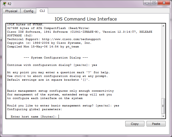
So what is setup mode?
Setup mode is available when a router is started for the first time. Like this below:
So what for?
To provide a basic configuration for the router. Packet Tracer supports only basic management setup, which limits you to configuring only a single interface that can connect to a management system that will supply the remainder of the configuration. Router R2 is an existing router that has been added to the network. We will clear any existing configuration and use setup mode to connect it to router R1.
So what can we do in setup mode?
And after you enter picture 2 with 'yes' you will get this picture below:
 |
| Picture 1 |
So what for?
To provide a basic configuration for the router. Packet Tracer supports only basic management setup, which limits you to configuring only a single interface that can connect to a management system that will supply the remainder of the configuration. Router R2 is an existing router that has been added to the network. We will clear any existing configuration and use setup mode to connect it to router R1.
So what can we do in setup mode?
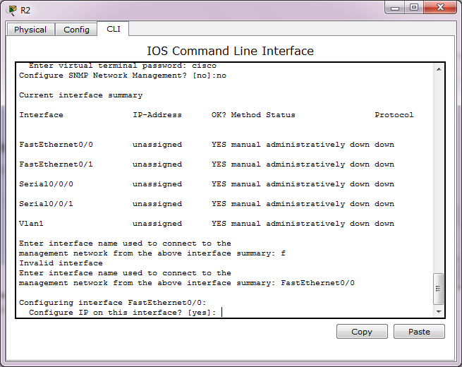
- Confirm the use of the configuration dialog by entering yes.
- Enter basic management setup by entering yes (this is the only option supported by Packet Tracer).
- Enter R2 for the host name.
- Enter class for the enable secret.
- Enter cisco for the enable password.
- Enter cisco for the virtual terminal password.
- Enter FastEthernet0/0 for the interface name used to connect to the management network.
- Confirm the configuration of IP on the interface.
- Enter 192.168.2.2 for the interface IP address.
- Accept the default subnet mask.
- Accept the default to save this configuration to nvram and exit.
 |
| Picture 2 |
 |
| Picture 3 |
 |
| Picture 4 |
 |
| Picture 5 |
 |
| Picture 6 |
 |
| Picture 8 |
 |
| Picture 9 |
 |
| Picture 10 |
 |
| Picture 11 |
 |
| Picture 12 |
 |
| Picture 13 |
Saturday, 21 November 2015
Routing loops
Causing you can't ping / telnet and when you do traceroute from PC its like this below:
So what is the final cause of this problem? It is the misconfigured static route within two router or within a pair of router.
So what is the final cause of this problem? It is the misconfigured static route within two router or within a pair of router.
Friday, 20 November 2015
How to summerize address
How can I use interfaces loopback to summerize 2 or more network or subnet address?
We can use interface loopback to summerize 2 or more network or subnet address that been given to us to summerize.
Ok, for you want to summerize these 3 subnetwork addresses:
172.30.1.0/24
172.30.2.0/24
172.30.3.0/24
First, assign each interfaces
R1(config)#int lo0
R1(config-if)# ip address 172.30.1.1 255.255.255.0
R1(config)#int lo1
R1(config-if)# ip address 172.30.2.1 255.255.255.0
R1(config-if)# int lo2
R1(config-if)# ip address 172.30.3.1 255.255.255.0
and then show ip route, like below:
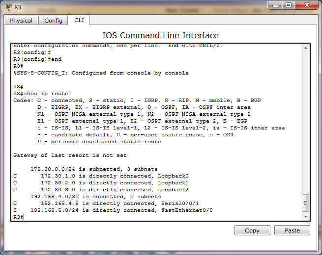
Thursday, 19 November 2015
RIP
Lets make all of our router's network databases is same or synchronized and let RIP chooses what better path.
Specifying the network:
1. For each router that want to RIP process routing, configure their directly-connected network just at their classful boundary. No use if you define them at their classless address. Like below:
R1(config)# router rip
R1(config-router)# network 192.168.1.0
R1(config-router)# network 192.168.2.0
Configure RIP's passive interface:
1. For interfaces in each router, define what interface that should be blocked from sending RIP's packet a.k.a don't participate in sending packet of RIP update about network update. So we continue/add our previous config above with below:
R1(config-router)#passive-interface f0/0
But before we add that config/command, we need to show ip protocols, like below:
R1(config-router)# passive-interface fa0/0
And show ip protocols again, like below:
Watch for automatic-summerization.
This is the hardest part to understand with RIPv1. So watch it.
Discontiguos network means is not using subnets of one major network.
Contiguous networks means is using subnets of one major network.
RIP isn't good/better at discontiguos network.
If your networks is inside/using one same major network of IP address, then RIPv1 is good to go. Like this:
172.16.0.0/19
172.16.32.0/19
172.16.64.0/29
172.16.96.0/29
172.16.128.0/29
But if your networks isn't inside/using one same major network, then RIPv1 is wreck/error/fail. For instance like this:
172.16.0.0/19
172.16.32.0/19
172.16.64.0/19
192.168.1.0/24
192.168.2.0/24
I even made a quiz/contest, who able to make above network work with RIPv1 I will give IDR 100.000.
Or, you can use discontiguous networks, but you need to arrange the placement of those networks carefully. Or, just don't use subnets with RIPv1. What I mean is use classful address, don't do subnetting.
Another solution to RIPv1 is using really different major network, like below:
192.168.1.0/24
192.168.2.0/24
192.168.3.0/24
192.168.4.0/24
192.168.5.0/24
While, RIPv2 have 2 options, RIPv1 have 1. Poor RIPv1.
Everytime you given a topology that contains:
Ok. Thats it for automatic summerization. Our next guest is propagating default-route.
Propagating default-route
If you have a router that have an internet connection then that router is a what-we-call a boundary-router.
To tell a router to advertises its default-route is simple. Just use "default-information originate" inside the mode of router RIP configuration mode. Like below:
R1(config)# router rip
R1(config-router)# default-information originate
Specifying the network:
1. For each router that want to RIP process routing, configure their directly-connected network just at their classful boundary. No use if you define them at their classless address. Like below:
R1(config)# router rip
R1(config-router)# network 192.168.1.0
R1(config-router)# network 192.168.2.0
Configure RIP's passive interface:
1. For interfaces in each router, define what interface that should be blocked from sending RIP's packet a.k.a don't participate in sending packet of RIP update about network update. So we continue/add our previous config above with below:
R1(config-router)#passive-interface f0/0
But before we add that config/command, we need to show ip protocols, like below:
R1#show ip protocols
Routing Protocol is "rip"
Sending updates every 30 seconds, next due in 26 seconds
Invalid after 180 seconds, hold down 180, flushed after 240
Outgoing update filter list for all interfaces is not set
Incoming update filter list for all interfaces is not set
Redistributing: rip
Default version control: send version 1, receive any version
Interface Send Recv Triggered RIP Key-chain
FastEthernet0/0 1 2 1
Serial0/0/0 1 2 1
Automatic network summarization is in effect
Maximum path: 4
Routing for Networks:
192.168.1.0
192.168.2.0
Passive Interface(s):
Routing Information Sources:
Gateway Distance Last Update
192.168.2.2 120 00:00:18
Distance: (default is 120)
And now assign:Routing Protocol is "rip"
Sending updates every 30 seconds, next due in 26 seconds
Invalid after 180 seconds, hold down 180, flushed after 240
Outgoing update filter list for all interfaces is not set
Incoming update filter list for all interfaces is not set
Redistributing: rip
Default version control: send version 1, receive any version
Interface Send Recv Triggered RIP Key-chain
FastEthernet0/0 1 2 1
Serial0/0/0 1 2 1
Automatic network summarization is in effect
Maximum path: 4
Routing for Networks:
192.168.1.0
192.168.2.0
Passive Interface(s):
Routing Information Sources:
Gateway Distance Last Update
192.168.2.2 120 00:00:18
Distance: (default is 120)
R1(config-router)# passive-interface fa0/0
And show ip protocols again, like below:
R1#show ip protocols
Routing Protocol is "rip"
Sending updates every 30 seconds, next due in 18 seconds
Invalid after 180 seconds, hold down 180, flushed after 240
Outgoing update filter list for all interfaces is not set
Incoming update filter list for all interfaces is not set
Redistributing: rip
Default version control: send version 1, receive any version
Interface Send Recv Triggered RIP Key-chain
Serial0/0/0 1 2 1
Automatic network summarization is in effect
Maximum path: 4
Routing for Networks:
192.168.1.0
192.168.2.0
Passive Interface(s):
FastEthernet0/0
Routing Information Sources:
Gateway Distance Last Update
192.168.2.2 120 00:00:00
Distance: (default is 120)
Notice that now FastEthernet0/0 is gone from interface list (list of interface that participate in RIP routing protocol a.k.a active interfaces).Routing Protocol is "rip"
Sending updates every 30 seconds, next due in 18 seconds
Invalid after 180 seconds, hold down 180, flushed after 240
Outgoing update filter list for all interfaces is not set
Incoming update filter list for all interfaces is not set
Redistributing: rip
Default version control: send version 1, receive any version
Interface Send Recv Triggered RIP Key-chain
Serial0/0/0 1 2 1
Automatic network summarization is in effect
Maximum path: 4
Routing for Networks:
192.168.1.0
192.168.2.0
Passive Interface(s):
FastEthernet0/0
Routing Information Sources:
Gateway Distance Last Update
192.168.2.2 120 00:00:00
Distance: (default is 120)
Watch for automatic-summerization.
This is the hardest part to understand with RIPv1. So watch it.
Discontiguos network means is not using subnets of one major network.
Contiguous networks means is using subnets of one major network.
RIP isn't good/better at discontiguos network.
If your networks is inside/using one same major network of IP address, then RIPv1 is good to go. Like this:
172.16.0.0/19
172.16.32.0/19
172.16.64.0/29
172.16.96.0/29
172.16.128.0/29
But if your networks isn't inside/using one same major network, then RIPv1 is wreck/error/fail. For instance like this:
172.16.0.0/19
172.16.32.0/19
172.16.64.0/19
192.168.1.0/24
192.168.2.0/24
I even made a quiz/contest, who able to make above network work with RIPv1 I will give IDR 100.000.
Or, you can use discontiguous networks, but you need to arrange the placement of those networks carefully. Or, just don't use subnets with RIPv1. What I mean is use classful address, don't do subnetting.
Another solution to RIPv1 is using really different major network, like below:
192.168.1.0/24
192.168.2.0/24
192.168.3.0/24
192.168.4.0/24
192.168.5.0/24
While, RIPv2 have 2 options, RIPv1 have 1. Poor RIPv1.
Everytime you given a topology that contains:
Ok. Thats it for automatic summerization. Our next guest is propagating default-route.
Propagating default-route
If you have a router that have an internet connection then that router is a what-we-call a boundary-router.
To tell a router to advertises its default-route is simple. Just use "default-information originate" inside the mode of router RIP configuration mode. Like below:
R1(config)# router rip
R1(config-router)# default-information originate
NTP
Lets make all our LAN's network-devices, PCs or SmartTV's time or clock or watches is same or synchronized and keep it same or synchronized until forever.In essence, in your LAN, dedicates a/one device as a NTP master and other devices in your LAN as client NTP.
Your-LAN NTP master cling to outside/public/internet's NTP master and your-LAN client NTP cling into your-LAN NTP master. Thats it.
So, for our LAN first we define R1 as our dedicated NTP master that serve the rest of our LAN's devices as follows:
R1#config terminal
R1(config)# ntp server time.microsoft.com
You can choose your own preferred NTP server by the way. You can just google for it or you can obtain a list of publicly accessible NTP servers here: www.ntp.org.
As for now, you can see that R1 is commanded to use outside's/internet's time server as its time/ntp server that is: time.microsoft.com in our case. You need internet connection to be able to connect to time.microsoft.com server and off course your router need to have dns server address and also able to ping the name: time.microsoft.com. If you don't use dns server, you can directly type the NTP server's in IP address format. For instance:
R1(config)#ntp server 192.168.1.1
R1(config)#
So now lets check its time, as follows:
R1#show clock
07:53:57.922 UTC Thu Nov 19 2015
Thats still not correct! What we missing is 'setting up the timezone of our own', so now lets add below command:07:53:57.922 UTC Thu Nov 19 2015
R1(config)# clock timezone INDONESIA +7
and then show clock again, as follows:
R1#show clock
15:05:49.860 INDONES Thu Nov 19 2015
Now its match. Indeed it is 3 PM now.
Congratulations..
NTP can be used to setting the clock of Cisco devices. But, not just Cisco devices, your Windows or Linux devices can also use NTP to set up their clock.
You can use a command like: show ntp associations, but whats that good for you is just wether the router have been synchronized or not with the ntp outside. Like below:
R1#show ntp associations
address ref clock st when poll reach delay offset disp
*~104.209.134.106 129.6.15.30 2 38 64 377 269.45 17.997 18.285
+~103.31.248.249 203.160.128.3 3 29 64 377 51.373 39.953 2.909
* sys.peer, # selected, + candidate, - outlyer, x falseticker, ~ configured
Right at the very bottom is * sys.peer, # selected, + candidate, - outlyer, x falseticker, ~ configured.
R1#show ntp status
Clock is synchronized, stratum 3, reference is 104.209.134.10
nominal freq is 250.0000 Hz, actual freq is 249.9997 Hz, precision is 2**28
reference time is D9F80E87.6F85B6AD (16:01:59.435 INDONES Thu Nov 19 2015)
clock offset is 23.9173 msec, root delay is 300.02 msec
root dispersion is 115.20 msec, peer dispersion is 20.16 msec
loopfilter state is 'CTRL' (Normal Controlled Loop), drift is 0.000001037 s/s
system poll interval is 64, last update was 301 sec ago.
R1#show ntp status
Clock is unsynchronized, stratum 16, no reference clock
nominal freq is 250.0000 Hz, actual freq is 249.9997 Hz, precision is 2**28
reference time is D9F80E87.6F85B6AD (16:01:59.435 INDONES Thu Nov 19 2015)
clock offset is 0.0000 msec, root delay is 0.00 msec
root dispersion is 0.50 msec, peer dispersion is 0.00 msec
loopfilter state is 'CTRL' (Normal Controlled Loop), drift is 0.000001037 s/s
system poll interval is 64, last update was 398 sec ago.
RADIUS
Make a device consult/ask/query a 'boss' about someone credential, "Boss, is it valid or not valid?"
Slightly hard or complex to setup it just because it had many steps. So, be patience.
Summary steps
1. Configure a device so it know who is the 'boss' and how to authenticate user.
2. Configure the boss to know who is his employee.
3. Try telnet to that device
So there are 3 components of this system, such as
1. The boss or employer or radius-server in this case.
2. Employee or switch or router in this case.
3. And user or PC.
We call radius-server as employer or the 'boss' in this case and a network-device as employee and user that wants to telnet to that network-device or employee as user.
On any network-device or employee setup below:
R1(config)# radius-server 192.168.2.2 aloh@
R1(config)# aaa new-authentication
R1(config)# aaa authentication login RADIUS group radius local
R1(config)# line vty 0 15
R1(config-line)# login authentication RADIUS
R1(config-line)# end
And, on the 'boss'/employer setup this by:
1. Click on Server icon
2. Click on tab Config
3. Click on menu AAA
4. And start to fill it like this:
Now, on the user setup this by:
1. Click on PC2 Icon
2. Click menu Command Prompt
3. Type this: telnet 192.168.4.1
4. And fill it like this:
Username: Totz
Password: Perjuangan9
Just like below picture:
Off course the fundamental thing to the system is the employee(s) or R1 in this case need to be sucessfully ping to the RADIUS server at first. Otherwise, RADIUS system will fail and user authentication will revert to each local device's username and password authentication method.
So, try to ping the 'boss/employer' RADIUS server from R1 or any network device employee at first like below:
And when you get that result/output, you are safe. Otherwise you need to troubleshoot why it fail.
And second step, make sure there is nothing that block your connection to the 'boss' on port 1654.
We already solve/mitigate/prepare for this issue by adding a keyword 'local' on the authentication list definition (step 3). Without this 'local' keyword, authentication will just fail without any second method/plan in ready/avaliable to our system/network. So in effect without keyword 'local', user will unable to enter/telnet into the router (R1) until the RADIUS server is back online/pingable again.
By the way, to simulate the down of the RADIUS server, you can put into 'off' the AAA service (look for picture 1) and when User try to enter/telnet/ssh into the router and fill in the username and password, the login process will return: % Login invalid.
And here is the pkt file: https://drive.google.com/open?id=0B5Sl0ZstVGYFYnNlTVBYVnFBVzQ
Slightly hard or complex to setup it just because it had many steps. So, be patience.
Summary steps
1. Configure a device so it know who is the 'boss' and how to authenticate user.
2. Configure the boss to know who is his employee.
3. Try telnet to that device
So there are 3 components of this system, such as
1. The boss or employer or radius-server in this case.
2. Employee or switch or router in this case.
3. And user or PC.
We call radius-server as employer or the 'boss' in this case and a network-device as employee and user that wants to telnet to that network-device or employee as user.
On any network-device or employee setup below:
R1(config)# radius-server 192.168.2.2 aloh@
R1(config)# aaa new-authentication
R1(config)# aaa authentication login RADIUS group radius local
R1(config)# line vty 0 15
R1(config-line)# login authentication RADIUS
R1(config-line)# end
And, on the 'boss'/employer setup this by:
1. Click on Server icon
2. Click on tab Config
3. Click on menu AAA
4. And start to fill it like this:
 |
| Picture 1 |
Now, on the user setup this by:
1. Click on PC2 Icon
2. Click menu Command Prompt
3. Type this: telnet 192.168.4.1
4. And fill it like this:
Username: Totz
Password: Perjuangan9
Just like below picture:
Off course the fundamental thing to the system is the employee(s) or R1 in this case need to be sucessfully ping to the RADIUS server at first. Otherwise, RADIUS system will fail and user authentication will revert to each local device's username and password authentication method.
So, try to ping the 'boss/employer' RADIUS server from R1 or any network device employee at first like below:
R1#ping 192.168.2.2
Type escape sequence to abort.
Sending 5, 100-byte ICMP Echos to 192.168.2.2, timeout is 2 seconds:
!!!!!
Success rate is 100 percent (5/5), round-trip min/avg/max = 0/0/1 ms
Type escape sequence to abort.
Sending 5, 100-byte ICMP Echos to 192.168.2.2, timeout is 2 seconds:
!!!!!
Success rate is 100 percent (5/5), round-trip min/avg/max = 0/0/1 ms
And when you get that result/output, you are safe. Otherwise you need to troubleshoot why it fail.
And second step, make sure there is nothing that block your connection to the 'boss' on port 1654.
We already solve/mitigate/prepare for this issue by adding a keyword 'local' on the authentication list definition (step 3). Without this 'local' keyword, authentication will just fail without any second method/plan in ready/avaliable to our system/network. So in effect without keyword 'local', user will unable to enter/telnet into the router (R1) until the RADIUS server is back online/pingable again.
By the way, to simulate the down of the RADIUS server, you can put into 'off' the AAA service (look for picture 1) and when User try to enter/telnet/ssh into the router and fill in the username and password, the login process will return: % Login invalid.
And here is the pkt file: https://drive.google.com/open?id=0B5Sl0ZstVGYFYnNlTVBYVnFBVzQ
Time based access-list
Give when and how long to an access-list / scheduled access-list.
I want user can't go to web for time 8.00 to 17.00. How can I do that?
I want user can't go to web for time 8.00 to 17.00. How can I do that?
Wednesday, 18 November 2015
Reflexive Access List
Reflect & Evaluate what is reflected.
Below will allow icmp (ping) traffic , any tcp traffic and udp DNS traffic to go out.
Ip access-list extended outbound_acl
permit icmp any any
permit tcp any any reflect tcp-traffic
permit udp any any eq 53 reflect dns-traffic timeout 10
IP access-list extended inbound_acl
permit icmp any any
evaluate tcp-traffic
evaluate dns-traffic
exit
conf t
int s0/0/0
# ip access-group outbound_acl out
# ip access-group inbound_acl in
Lock and Key Access List
I am on Internet. I want to ftp to my Raspberry pi behind my Internet's router. I have bought a public IP address from my ISP. What should I do?
You must telnet first then you get an access to the internal.
You must telnet first then you get an access to the internal.
Port Numbers and Protocols of Oracle Components
I have an assignment to allow Oracle database connection outbound through a router to the Internet. So what ports that I should allow?
Table E-1 Ports Used in Oracle Components
Table E-1 Ports Used in Oracle Components
| Component and Description | Default Port Number | Port Range | Protocol |
|---|---|---|---|
| Oracle SQL*Net Listener Allows Oracle client connections to the database over Oracle's SQL*Net protocol. You can configure it during installation. To reconfigure this port, use Net Configuration Assistant. |
1521 | 1521 | TCP |
| Data Guard Shares the SQL*Net port and is configured during installation. To reconfigure this port, use Net Configuration Assistant to reconfigure the Oracle SQL*Net listener. |
1521 (same value as the listener) | 1521 | TCP |
| Connection Manager Listening port for Oracle client connections to Oracle Connection Manager. It is not configured during installation, but can be configured using Net Configuration Assistant. |
1630 | 1630 | TCP |
| Oracle Management Agent HTTP port for Enterprise Management Agent. It is configured during installation. "Changing the Oracle Enterprise Management Agent Port" explains how to modify its port number |
3938 | 1830–1849 | HTTP |
| Oracle Enterprise Manager Database Console HTTP port for Enterprise Manager Database Control. It is configured during installation. "Changing the Oracle Enterprise Manager Database Console Ports" explains how to modify its port number. |
1158 | 5500–5519 | TCP/HTTP |
| Oracle Enterprise Manager Database Console RMI port for Enterprise Manager Database Control. It is configured during installation."Changing the Oracle Enterprise Manager Database Console Ports" explains how to modify its port number. |
5520 | 5520–5539 | TCP |
| Enterprise Manager Database Console JMS port for Enterprise Manager Database Control. It is configured during installation. "Changing the Oracle Enterprise Manager Database Console Ports" explains how to modify its port number. |
5540 | 5540–5559 | TCP |
| iSQL*Plus HTTP port for iSQL*Plus. The port number is automatically assigned during installation. "Changing the iSQL*Plus Ports" explains how to change its port number. |
5560 | 5560–5579 | TCP/HTTP |
| iSQL*Plus RMI port for iSQL*Plus. The port number is automatically assigned during installation."Changing the iSQL*Plus Ports" explains how to change its port number. |
5580 | 5580–5599 | TCP |
| iSQL*Plus JMS port for iSQL*Plus. The port number is automatically assigned during installation. "Changing the iSQL*Plus Ports" explains how to change its port number. |
5600 | 5600–5619 | TCP |
| Oracle Ultra Search HTTP port for Oracle Ultra Search. Its port number is assigned automatically when you install Oracle Ultra Search, by using the Custom installation type. "Changing the Oracle Ultra Search Ports" explains how to change its port number. |
5620 | 5620–5639 | TCP/HTTP |
| Oracle Ultra Search RMI port for Oracle Ultra Search. Its port number is assigned automatically when you install Oracle Ultra Search, by using the Custom installation type. "Changing the Oracle Ultra Search Ports" explains how to change its port number. |
5640 | 5640–5659 | TCP |
| Oracle Ultra Search JMS port for Oracle Ultra Search. Its port number is assigned automatically when you install Oracle Ultra Search, by using the Custom installation type. "Changing the Oracle Ultra Search Ports" explains how to change its port number. |
5660 | 5660–5679 | TCP |
| Oracle XML DB The Oracle XML DB HTTP port is used if Web-based applications need to access an Oracle database from an HTTP listener. It is configured during installation, but you cannot view it afterward. "Changing the Oracle XML DB Ports" explains how to change its port number. |
Dynamic | Dynamic | HTTP |
| Oracle XML DB The Oracle XML DB FTP is used when applications need to access an Oracle database from an FTP listener. It is configured during installation, but you cannot view it afterward. "Changing the Oracle XML DB Ports" explains how to change its port number. |
Dynamic | Dynamic | FTP |
| Oracle Real Application Clusters (Local Host: Windows only) - On Rac is configured by default - Is configurable |
61000 | 61000–61300 | TCP |
| Oracle Real Application Clusters (Cluster Interconnect: Windows only) - On RAC is configured by default - Is configurable |
11000 | 11000–26000 | TCP |
| Oracle Real Application Clusters (UNIX) The port number is assigned automatically during installation. You cannot view or modify it afterward. |
Dynamic | Dynamic | UDP |
| Oracle Clusterware CRS daemon (Oracle Cluster Ready Services Daemon) internode connection. The port number is assigned automatically during installation. You cannot view or modify it afterward. |
49896 | 49896 | TCP |
| Cluster Synchronization Service (CSS) CSS daemon internode connection for the GM layer. The port number is assigned automatically during installation. You cannot view or modify it afterward. |
49895 | 49895 | TCP |
| Oracle Cluster Registry The port number is assigned automatically during installation. You cannot view or modify it afterward. |
Dynamic | Dynamic | TCP |
| Oracle Event Manager The port number is assigned automatically during installation. You cannot view or modify it afterward. |
49897 | 49897–49898 | TCP |
| Cluster Manager The port number is assigned automatically during installation. You cannot view or modify it afterward. |
Dynamic | Dynamic | TCP |
Instalasi email client: Thunderbird

Big step:
1. Download software-nya
2. Install software-nya
3. Konfigurasi software-nya
Penjelasan
1. Download email client/software thunderbird (32,5MB) di https://www.mozilla.org/en-US/thunderbird/
2. Instal software diatas ke dalam laptop.
3. Konfigurasi alamat POP3 dan SMTP ke google
POP3:
SMTP:
POP3 dan IMAP
POP3 and IMAP are two different protocols (methods) used to access email.Of the two, IMAP is the better option - and the recommended option - when you need to check your emails from multiple devices, such as a work laptop, a home computer, or a tablet, smartphone, or other mobile device. Tap into your synced (updated) account from any device with IMAP.
POP3 downloads email from a server to a single computer, then deletes it from the server. Because your messages get downloaded to a single computer or device and then deleted from the server, it can appear that mail is missing or disappearing from your Inbox if you try to check your mail from a different compu
What is safe mode?
What is safe mode?
Safe
mode is a troubleshooting option for Windows that starts your computer in a limited
state. Only the basic files and drivers
necessary to run Windows are started. The
words Safe Mode appear in the corners of your monitor to
identify which Windows mode you're using.
If an existing problem doesn't reappear when you start in safe
mode, you can eliminate the default
settings and basic device drivers as possible causes. If you don't know the
cause of the problem, you can use the process of elimination to help you find
the problem. Try starting all of the programs you commonly use, including the
programs in your Startup folder, one by one to see if a program might be the
cause of the problem.
If your computer automatically starts in safe mode without
prompting, a problem with your computer might be preventing Windows from starting normally. If you think the
cause of the problem might be a recently installed program or device, try using
Recovery in Control Panel.
Di Safe mode with networking:
- Bisa nonton youtube tapi tidak ada suara.
- Bisa intenetan, bisa ping ke local network.
- Bisa jalankan program Microsoft Word, Adobe Reader PDF.
- Bisa jalankan program network simulator seperti: GNS3, Cisco Packet Tracer
- Tidak bisa menjalankan Fitur NTP.
- Tidak bisa menjalankan Operating System berbasis VMWare.
Tuesday, 17 November 2015
Install GNS3
Installation:
Big Steps:
1. Download
2. Instal
3. Select images for the GNS3
4. Drag your router
5. Start/Run
6. Start configuration
1. Download source code from www.gns3.com
2.
Image files:
https://drive.google.com/open?id=0B5Sl0ZstVGYFbjY3dS04cG94YVE
https://drive.google.com/open?id=0B5Sl0ZstVGYFa2ZNRHc0bTB3d2M
https://drive.google.com/open?id=0B5Sl0ZstVGYFa2ZNRHc0bTB3d2M
Cautions:
1. GNS3 bisa dijalankan pada mode "Safe Mode With Networking" Windows.2. Idle PC bisa dihitung/dikalkulasi setelah perangkat di jalankan.
3. Config-nya bisa di save atau di-export. Asal tiap device/perangkat di assign command: copy run start terlebih dahulu.
Monday, 16 November 2015
How to embed a SWF file in a html page?
<object width="100" height="100">
    <param name="movie" value="file.swf">
    <embed src="file.swf" width="100" height="100">
    </embed>
</object>What is CDATA in HTML?
Since it is useful to be able to use less-than signs (<) and ampersands (&) in web page scripts, and to a lesser extent styles, without having to remember to escape them, it is common to use CDATA markers around the text of inline and elements in XHTML documents. But so that the document can also be parsed by HTML parsers, which do not recognise the CDATA markers, the CDATA markers are usually commented-out, as in this JavaScript example:
<script type="text/javascript">
//<![CDATA[
document.write("<");
//]]>
</script>Sunday, 15 November 2015
Soal-soalJaringan IP
1. A, 1. Kalau dibalik jadi? 1, A.
2. A, 1, 2. Kalau yang bisa dibalik hanya 2 karakter saja jadi apa? 1, A, 2.
2. Kalau nomor kamar dari 1 - 9. Berapa jumlah kamar? 10
3. Kalau nomor kamar dari 0 - 9. Berapa jumlah kamar? 10 + 1 = 11
4. Kalau nomor kamar dari 1 - 19. Berapa jumlah kamar? 20!
5. Kalau nomor kamar dari 0 - 19. Berapa jumlah kamar? 21!
Guide membuat access-list (ACL)
1. Deny dulu baru permit. Denying the network traffic from accessing another network comes before permitting all other traffic.
2. Selalu tempatkan access-list standard dekat ke network/host yang mau di deny
3. Selalu tempatkan/urutkan most specific ke least specific.
4. Kalau tidak ada mention port, mending pakai access-list standard
5. Kalau ada mention port, pakai access-list extended
6. Numbered atau named terserah, kalau yang lebih mudah di edit named.
7. Untuk nge-view atau examine access-list jangan pakai show run tapi lebih enak pakai show access-list atau show ip access-list
Contoh:
• For the 192.168.10.0/24 network, block Telnet access to all locations and TFTP access to the corporate Web/TFTP server at 192.168.20.254. All other access is allowed.
• For the192.168.11.0/24 network, allow TFTP access and web access to the corporate Web/TFTP server at 192.168.20.254. Block all other traffic from the 192.168.11.0/24 network to the 192.168.20.0/24 network. All other access is allowed.
Terjemahan:
Dengan bahasa lain / yang lebih sederhana:
Network 192.168.10.0/24 bisa akses ke semua kecuali telnet ke semua lokasi dan akses TFTP ke corporate Web/TFTP server.
Network 192.168.11.0/24
Penjabaran:
For 192.168.10.0/24
Block:
2. Selalu tempatkan access-list standard dekat ke network/host yang mau di deny
3. Selalu tempatkan/urutkan most specific ke least specific.
4. Kalau tidak ada mention port, mending pakai access-list standard
5. Kalau ada mention port, pakai access-list extended
6. Numbered atau named terserah, kalau yang lebih mudah di edit named.
7. Untuk nge-view atau examine access-list jangan pakai show run tapi lebih enak pakai show access-list atau show ip access-list
Contoh:
• For the 192.168.10.0/24 network, block Telnet access to all locations and TFTP access to the corporate Web/TFTP server at 192.168.20.254. All other access is allowed.
• For the192.168.11.0/24 network, allow TFTP access and web access to the corporate Web/TFTP server at 192.168.20.254. Block all other traffic from the 192.168.11.0/24 network to the 192.168.20.0/24 network. All other access is allowed.
Terjemahan:
- Untuk network 192.168.10.0/24, blok akses Telnet ke semua lokasi dan akses TFTP ke corporate Web/TFTP server di 192.168.20.254. Semua akses lain diperbolehkan.
- Untuk network 192.168.11.0/24, izinkan/bolehkan akses TFTP dan akses web ke corporate Web/TFTP server. Blok semua trafik lain dari 192.168.11.0/24 (network ini) ke network 192.168.20.0/24. Semua akses lain diperbolehkan.
Dengan bahasa lain / yang lebih sederhana:
Network 192.168.10.0/24 bisa akses ke semua kecuali telnet ke semua lokasi dan akses TFTP ke corporate Web/TFTP server.
Network 192.168.11.0/24
Penjabaran:
For 192.168.10.0/24
Block:
- Telnet access to all locations
- TFTP access to the corporate Web/TFTP server 192.168.20.254
- All other access (Mail, Database, Ping/ICMP)
For 192.168.11.0/24
Block:
- Block all other traffic from the 192.168.11.0/24 to the 192.168.20.0/24 network
Permit:
- TFTP access and web access to the corporate Web/TFTP server at 192.168.20.254
Access-list
R1(config)#access-list 100
Acitivty: Mengamankan jaringan dengan menggunakan ACL
Activity 1
1. An access Control List (ACL) is a router configuration script that controls whether a router will ____ or ___ packets based on criteria found in the packet header.
2. ACL are often used in ___ routers that are positioned between your internal network and external network.
3. A router with three active interface and two network protocols (IP and IPX) can have as many as ___ active ACLs.
4. For inbound ACLs, incoming packets are processed ___ they are routed to an outbound interface.
5. For outbound ACLs, incoming packets are processed ___ they are routed to an outbound interface.
6. At the end of every access-list is an implied ___ all traffic criteria statement. Therefore, if a packet does not match any of your criteria statements, the packet will be ___
permit, six, before, blocked, allowed, while, deny, firewall, after, three, twelve.
Answer:
1. Permit, Deny
2. Firewall
3. Twelve
4. Before
5. After
6. Deny, Blocked
Activity 2
1. Can filter traffic based on source IP address: Standard dan Extended
2. Can filter traffic based on destination IP address: hanya Extended saja
3. Can filter traffic based on protocol type: hany Extended saja
4. Uses number 1 - 99: Standard
5. Uses number 100 - 199: Extended
6. Uses number 1300 - 1999: Standard
7. Can use a name insted of a number: Standard and Extended
Activity 3
Network policy #1: Use a standard ACL to stop the 192.168.1.0/24 network from accessing the Internet via ISP
Network policy #2: Use an extended ACL to stop the 192.168.30.0/24 network from accessing the Web/TFTP server.
Saturday, 14 November 2015
URL must not have a path (example.com/path) or subdomain
(subdomain.example.com).<a
href='//support.google.com/adsense/answer/2784438?hl=en_US&utm_source=aso&utm_medium=link&utm_campaign=ww-ww-et-asfe_'
target='_blank'> Learn more</a
If you wish to show ads on your non-host websites, you will need to submit a one-time application via the form below.
Important: In order for your application to be reviewed, you must place your ad code on one or more webpages at the URL you enter below. Note that blank ads will be shown until your application is approved.
Once your application has been approved, you may place your ad code on any website that you own without any further approvals. If your application is not approved, you will still be able to show ads on host sites and may apply again in the future.
Beberapa tips and trick Cisco switch dan router
1. Routing tabel bisa digunakan sebagai alat pensumerisasi nomor jaringan
1. Create 1 atau 2 buah interface loopback
2. Assign nomor jaringan yang ingin disumerisasi ke interface loopback yang baru saja di create
3. Asssign show ip route
2. Menentukan reference bandwidth cost dari fitur OSPF pada router-router jaringan
Interface cost = reference bandwith / interface bandwidth
2. Access-list sebagai menentukan
4. Cara menentukan root id dari fitur spanning-tree pada switch - switch jaringan
1. Telnet ke semua switch
2. Assign command: show spanning-tree brief di semua switch
3. Look for VLAN yang ingin dicari/diamati (VLAN target)
4. Lihat apakah semua portnya forward.
5.
5. Cara menentukan switch berhasil memforward atau tidak paket host
Thursday, 12 November 2015
Comparing 802.d and 802.w
Membandingkan kecepatan spanning-tree and pvst
Spanning-tree 802.1d
Algoritma:
1. show spanning-tree di semua switch
S1# show spanning-tree
S2# show spanning-tree
S3# show spanning-tree
2. Dari output / keluaran / hasil perintah-perintah diatas, tentukan switch mana yg jadi root bridge.
3. Dari output / keluaran / hasil perintah S2#show spanning-tree vlan 99 tentukan port mana yang blocking dan forwarding.
3. Test ping dari PC3 ke PC server
4. Cabut kabel fa0/1 switch 1 dan fa0/3 switch 1. Btw apakah status port fa0/1 pada switch 1 ini, dan apakah status fa0/3 pada switch 1 ini?
5. Kembali ke window PC3, berapa kali terjadi timeout?
6. Kembalikan kabel fa0/1 ke switch dan fa0/3 ke switch 1. Apakah terjadi timeout lagi?
Wednesday, 11 November 2015
Configuring RSTP
Task 8: Configure PVST Rapid Spanning Tree Protocol
Cisco has developed several features to address the slow convergence times associated with standard STP. PortFast, UplinkFast, and BackboneFast are features that, when properly configured, can dramatically reduce the time required to restore connectivity dramatically. Incorporating these features requires manual configuration, and care must be taken to do it correctly. The longer term solution is Rapid STP (RSTP), 802.1w, which incorporates these features among others. RSTP-PVST is configured as follows:
S1(config)#spanning-tree mode rapid-pvst
Configure all three switches in this manner.
S2(config)#spanning-tree mode rapid-pvst
S3(config)#spanning-tree mode rapid-pvst
Use the command show spanning-tree summary to verify that RSTP is enabled.
Tuesday, 10 November 2015
Swith kondisi baru/fresh/out-of-box/belum dikonfigurasi apa-apa
Gak ada/tersedia/punya kabel console.
1. 1 buah laptop
2. 3 buah switch seri 890
Target: setting LAB kamu sama dengan topologi jaringan
mengkonfigurasi masing-masing switch
Langkah percobaan:
1. set ip komputer/laptop ke ip 10.10.10.2 255.255.255.0
2. Nyalakan / power-up switch
2. tes ping dari laptop/komputer ke switch 10.10.10.1
3. telnet ke 10.10.10.1 (ini ip default switch)
4. Setting switch 1:
1. Nyalakan / power-up switch
2. Hubung kabel LAN antara port fa0/1 switch ke colokan LAN PC/laptop
3. Telnet dari PC/laptop ke 10.10.10.1 (ini ip default switch baru)
Basic setting
set hostname switch 1 : S1
set password line console 0: cisco, mode loginnya local.
set password line vty 0 15 cisco, mode loginnya local.
set enable secretnya: class
SVI
set interface vlan 99: 172.17.99.1 255.255.255.0
VTP
set vtp mode switch 1: server
set vtp domain name switch 1: Lab5
set vtp password switch 1: cisco
Tambahkan VLAN-VLAN
Tambahkan VLAN-VLAN berikut beserta namanya ke switch 1:
VLAN 10
VLAN 20
VLAN 30
VLAN 99
Trunking
Set mode interface fa0/1 - fa0/4 switch 1: trunking bukan access
Set native vlan untuk trunking interface fa0/1-fa0/4 switch 1: vlan 99
switch 2 : S2
set hostname switch 2: S2
set password line console 0: cisco, mode loginnya local.
set password line vty 0 15 cisco, mode loginnya local.
set enable secretnya: class
SVI
set interface vlan 99: 172.17.99.1 255.255.255.0
Set trunking
Set mode interfae fa0/1 - fa0/4 switch 2: trunking
Set native vlan untuk trunking interae fa0/1 - fa0/4 switch 2: vlan 99
Set access
Set access buat host PC
Set mode interface fa0/6 switch 2: access
VTP
set vtp mode switch 2: client
set vtp domain name switch 2: Lab5
set vtp password switch 2: cisco
switch 3 : S3
set hostname switch 3 : S3
set password line console 0: cisco, mode loginnya local.
set password line vty 0 15 cisco, mode loginnya local.
set enable secretnya: class
set interface vlan 99: 172.17.99.1 255.255.255.0
Set trunking
Set mode interface fa0/1 - fa0/4 switch 3: trunking
Set native vlan untuk trunking interface fa0/1-fa0/4 switch 3: vlan 99
Set VTP
set vtp mode switch 3: client
set vtp domain name switch 3: Lab5
set vtp password switch 3: cisco
Wipe/erase access-list 23 pada switch
S3(config)#no access-list 23
S2(config)#no access-list 23
S1(config)# no access-list 23
Pengkabelan
S1 fa0/1 ke S3 fa0/1
S1 fa0/2 ke S3 fa0/2
S1 fa0/3 ke S2 fa0/3
S1 fa0/4 ke S2 fa0/4
S2 fa0/2 ke S3 fa0/4
S2 fa0/1 ke S3 fa0/3
Menggambar topologi spanning-tree tiap VLAN dan menandai siapa root
Biasanya kalau priority tiap switch tidak berubah, yang jadi root adalah sama untuk setiap vlan topologi spanning-tree.
Ini menyebabkan jalur/path yang dipakai/diterapkan setiap vlan itu sama. Sehingga menyebabkan jalur redudansi idle / tidak terpakai / tidak termanfaatkan.
Ini bisa dilihat di show spanning-tree brief
S1# show spanning-tree brief
S2# show spanning-tree brief
S3# show spanning-tree brief
Jika semua vlan root bridge id nya sama, maka semua spanning-tree vlan menggunakan root switch yang sama.
Contoh:
spanning-tree vlan 1, root switchnya switch 1,
spanning-tree vlan 10 root switchnya switch 1 juga,
spanning-tree vlan 20 root switchnya switch 1 juga,
spanning-tree vlan 30 root switchnya switch 1 juga.
VLAN 1
VLAN 10
VLAN 20
VLAN 30
Cara mengamankan jaringan wifi
1. Mengurangi kekuatan dB sinyal
2. Menyembunyikan nama WLAN / hiding SSID
3. Memberi password masuk WLAN
4. Membatasi mac address yang boleh masuk WLAN
Sekian dari saya. Semoga bermanfaat.
Monday, 9 November 2015


Pernikahan bukan tentang sex
Pernikahan bukan hanya tentang sex.
Pernikahan itu menyatukan dua keluarga besar.
Jika kamu menikah, kamu harus mempunyai database yang lebih besar tentang nama-nama relatif (anggota keluarga) kamu. Jadi siap-siap menjadi lebih besar.
Bagi orang yang mempunyai kelainan anti-sosial sejak kecil, kamu harus belajar sejak dini mengingat nama-nama relatif kamu.
Spanning-tree
Steps/algorithm:
1. Chose/decide a root bridge
2. Set the chosen root bridge bridge priority. Because switch priority is the only variable the used as spanning-tree root bridge calculation.
3. Set spanning-tree port fast to every ports that connect the client to switch. Do not set spanning-tree to port(s) that connect to switch to switch.
Topology or network diagram:
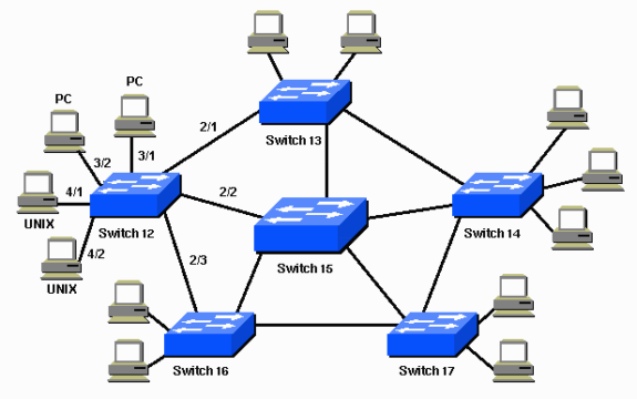
In above topology, switch 15 is suitable as backbone switch.
Source of reference: http://www.cisco.com/c/en/us/support/docs/lan-switching/spanning-tree-protocol/5234-5.html
Troubleshoot commands:
1. Chose/decide a root bridge
2. Set the chosen root bridge bridge priority. Because switch priority is the only variable the used as spanning-tree root bridge calculation.
3. Set spanning-tree port fast to every ports that connect the client to switch. Do not set spanning-tree to port(s) that connect to switch to switch.
Topology or network diagram:
In above topology, switch 15 is suitable as backbone switch.
Source of reference: http://www.cisco.com/c/en/us/support/docs/lan-switching/spanning-tree-protocol/5234-5.html
Troubleshoot commands:
- show spantree vlan_id —Shows
the current state of the spanning tree for this VLAN ID, from the
perspective of the switch on which you issue the command.
- show spantree summary —Provides a summary of connected spanning tree ports by VLAN.
- show spantree statistics —Shows spanning tree statistical information.
- show spantree backbonefast —Displays whether the spanning tree BackboneFast Convergence feature is enabled.
- show spantree blockedports —Displays only the blocked ports.
- show spantree portstate —Determines the current spanning tree state of a Token Ring port within a spanning tree.
- show spantree portvlancost —Shows the path cost for the VLANs on a port.
- show spantree uplinkfast —Shows the UplinkFast settings.
Subscribe to:
Posts (Atom)