For example, if you want to write a program that reads and analyzes
data from Twitter, you'd need to use the Twitter API, which would
specify the process for authentication, important URLs, classes,
methods, and so on.
Monday 31 August 2015
Building social networking profile
Sceleton
<!DOCTYPE html>
<html>
<head>
<title></title>
</head>
<body></body>
</html>
Instructions
<!DOCTYPE html>
<html>
<head>
<title></title>
</head>
<body></body>
</html>
Instructions
- Put your name between the
<title></title>tags. - Put a picture of yourself (or anything you like!) between the
<body></body>tags. If you can't think of a good picture, use this ninja: https://s3.amazonaws.com/codecademy-blog/assets/ninja_zpsa5dbe37a.jpg.
Configuring basic switch management
Task 1 connect to the switch via console
Task 2 Naviate through CLI modes
Task 3 Use Help Facility to configure the clock
Task 4 Access and configure command history
Task 5 Configure the boot sequence
Task 6 Configure PC and connect it to a switch
Task 7 Configure duplex and speed
Task 8 Manage the MAC address Table
Task 9 Manage the switch configuration file
Sunday 30 August 2015
I’ve trolled the internet looking for ways to configure the v92 modem
on a cisco 1811, and have managed to paste together pieces to make a
dialup connection from the router, please note this configuration will
not work with the aux port.
interface Async1
no ip address
ip nat outside
ip virtual-reassembly
encapsulation ppp
no ip route-cache cef
no ip route-cache
dialer in-band
dialer pool-member 1
dialer-group 1
async mode interactive
!
interface Dialer0
ip address negotiated
ip nat outside
ip virtual-reassembly
encapsulation ppp
no ip route-cache cef
no ip route-cache
dialer pool 1
dialer remote-name ***ISP NAME***
dialer idle-timeout 2000
dialer string ***NUMBER***
dialer hold-queue 10
dialer-group 1
no peer default ip address
ppp authentication pap chap callin
ppp chap hostname ***USERNAME***
ppp chap password 0 ***PASSWORD***
!
Dialer profiles separate logical configurations from the physical interfaces that receive or make calls. Because of this separation, interfaces such as ISDN, asynchronous modems, or synchronous serial connections can be shared by multiple dialer profile configurations.
DET
AILED STEPS
Purpose
Command or Action
Enters
the
configuration
mode
for
a
Gigabit
Ethernet
W
AN
interface
on
the
router
.
interface
type
number
Example:
Router(config)#
interface
gigabitethernet
1
Step 1
Sets
the
IP
address
and
subnet
mask
for
the
specified
Gigabit
Ethernet
interface.
ip
addr
ess
ip-addr
ess
mask
Example:
Router(config-if)#
ip
address
192.168.12.2
255.255.255.0
Step 2
Enables
the
Ethernet
interface,
changing
its
state
from
administratively
down
to
administratively
up.
no
shutdown
Example:
Router(config-if)#
no
shutdown
Step 3
Exits
configuration
mode
for
the
Gigabit
Ethernet
interface
and
returns
to
global
configuration
mode.
exit
Example:
Router(config-if)#
exit
Step 4
Example:
Router(config)#
Configuring a V
.92 Modem Interface
The
Cisco
891
ISR
has
a
V
.92
modem
backup
interface.
T
o
configure
this
interface,
perform
these
steps,
beginning
in
global
configuration
mode:
SUMMAR
Y STEPS
1.
interface
type
number
2.
ip
addr
ess
ip-addr
ess
mask
3.
encapsulation
ppp
4.
dialer
in-band
5.
dialer
string
dial-string
6.
dialer-gr
oup
gr
oup-number
7.
async
mode
dedicated
8.
exit
Cisco 800 Series Integrated Services Routers Software Configuration Guide
26
OL-31704-02
Basic Router Configuration
Configuring W
AN Interfaces
DET
AILED STEPS
Purpose
Command or Action
Enters
the
configuration
mode
for
a
V
.92
W
AN
interface
(serial
interface)
on
the
router
.
interface
type
number
Example:
Step 1
Example:
Router(config)#
interface
async
1
Sets
the
IP
address
and
subnet
mask
for
the
specified
V
.92
interface.
ip
addr
ess
ip-addr
ess
mask
Example:
Step 2
Example:
Router(config-if)#
ip
address
192.168.12.2
255.255.255.0
Sets
the
encapsulation
method
to
point-to-point
protocol
(PPP)
for
the
serial
interface.
encapsulation
ppp
Example:
Step 3
Example:
Router(config-if)#
encapsulation
ppp
Specifies
that
dial-on-demand
routing
(DDR)
is
supported.
dialer
in-band
Example:
Step 4
Example:
Router(config-if)#
dialer
in-band
Specifies
the
string
(telephone
number)
to
be
used
when
placing
a
call
from
the
interface.
dialer
string
dial-string
Example:
Step 5
Example:
Router(config-if)#
dialer
string
102
Configures
the
interface
to
belong
to
a
specific
dialing
access
group.
dialer-gr
oup
gr
oup-number
Example:
Step 6
Cisco 800 Series Integrated Services Routers Software Configuration Guide
OL-31704-02
27
Basic Router Configuration
Configuring W
AN Interfaces
Purpose
Command or Action
Example:
Router(config-if)#
dialer-group
1
Places
the
line
into
dedicated
asynchronous
mode
using
Serial
Line
Internet
Protocol
(SLIP)
or
PPP
encapsulation.
async
mode
dedicated
Example:
Step 7
Example:
Router(config-if)#
async
mode
dedicated
Exits
configuration
mode
for
the
V
.92
interface
and
returns
to
global
configuration
mode.
exit
Example:
Step 8
Example:
Router(config-if)#
exit
Example:
Router(config)#
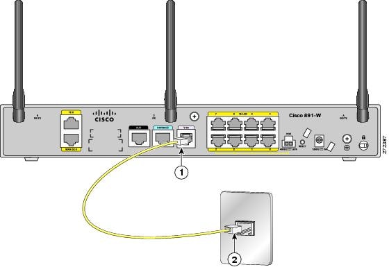 RJ.11
RJ.11Friday 28 August 2015
Thursday 27 August 2015
Wednesday 26 August 2015
<!DOCTYPE html>
<html>
<head>
<title>This is my own web page</title>
</head>
<body>
<h1>Totardo</h1>
<img src="https://s3.amazonaws.com/codecademy-blog/assets/ninja_zpsa5dbe37a.jpg" />
<p>Hello, my name is Totardo. I am the eldest of three brothers and sisters. I have 1 sister and 1 brother. </p>
<p>I learn about html daily. I use <a href="http://www.codecademy.com">codecademy</a> to learn about html. Sometimes I learn about <a href="http://www.cisco.com">cisco."</a></p>
<p>I want to be a succesful developer.</p>
</body>
</html>
Achievement:
1. Membuat kondisi dengan menggunakan if
2. Membuat operasi matematik ($biaya=$soto + $tehbotol
3. Membuat local variabel ($soto, $tehbotol)
4. Membuat html drop-down untuk jenis/variasi makanan dan jenis/variasi minuman
Tampilan sekrip .php nya:
1. Membuat kondisi dengan menggunakan if
2. Membuat operasi matematik ($biaya=$soto + $tehbotol
3. Membuat local variabel ($soto, $tehbotol)
4. Membuat html drop-down untuk jenis/variasi makanan dan jenis/variasi minuman
Tampilan sekrip .php nya:
Hello,<?php echo $_POST['name']?>
<br>

Jenis makanan adalah: <?php echo $_POST['makanan']
?><br>
Jenis minuman adalah: <?php echo $_POST

['minuman'];?>
<br>
<?php
$soto=10000;
$tehbotol=5000;
if ($_POST['makanan'] == "Soto"){
if($_POST['minuman']=="Tehbotol"){
$biaya = $soto+$tehbotol;
print "Biaya = ".$biaya;
}}
?>
Tampilan sekrip .html nya:
<form method="POST" action="wechat.php">
Name: <input type="text" name="name"> <br>
Jenis makanan: <select name="makanan">
<option value="Nasigoreng">Nasi Goreng</option>
<option value="Bakmie">Bakmi</option>
<option value="Soto">Soto</option>
</select> <br>
Minuman: <tab> <tab><select name="minuman">
<option value="Tehbotol">Teh Botol</option>
<option value="Aqua">Aqua</option>
<option value="Tehmanis">Teh Manis</option>
</select><br>
<input type="submit">
Tampilan GUI dari sekrip diatas:
Monday 24 August 2015
Saturday 22 August 2015
HTML
Styling:
1. Ngasih warna
2. Ngasih font size
3. Ngasih tipe font, contoh: trebuchet, verdana,
font-size
font-family
text-align
color
background-color
2. Quotations
Ngasih kutipan (quotations) contoh: <q>Aloha</q>
3. CSS
untuk styling html element
1. Ngasih warna latar
2. Ngasih warna teks
3. Ngasih
4. html5 Migration
Tentang perpindahan dari html 4 ke html 5. Perubahan tag divisi. Perubahan doctype. Perubahan html encoding.
Header, nav, section, aside,
5. html class
di "class" kan supaya sama di style kan.
contoh:
<head><style>
div.cities {
background-color:black;
color:white;
margin:20px;
padding:20px;
}
</style>
</head>
6. charset
untuk browser bisa tampil kan page html dengan bener web browser perlu mengetahui charcter set untuk digunakan.
ASCII adalah character set yang pertama kali digunakan sebagai character set.
Friday 21 August 2015
$ python
>>>1/2
>>>1/2.
integer: don't know decimal point
float : know decimal point (comma)
>>> print "hello"
>>> fish = 'tuna'
>>> len (fish)
>>> fish * 10
'tunatunatunatunatunatunatunatunatunatuna'
>>> help(len)
>>> dir()
>>> 1 == 1
True
>>> len(fish) == 4
True
>>> "a" == "a"
True
>>> "a" == "A"
False
>>> "a" != "z"
True
>>> 1 > 0
True
>>> 2 >= 3 (is 2 lebah besar atau sama dengan 3?)
False
>>> -1 < 0
True
>>> "H" in "Hello"
True
>>> "z" in "Hello"
False
>>> "z" not in "hello"
True
>>> x == 4
True
>>> len("")
>>> my_list = ["a", "b", "c"]
>>> len(my_list)
>>> my_list[0]
'a'
>>> my_list[1]
'b'
>>> my_list.append("d")
>>> my_list
['a', 'b', 'c', 'd']
>>>my_list.index("c")
>>> "a" in my_list
True
>>> "z" in my_list
False
>>> my_list[0:2] '[start:not including the second]
Wednesday 19 August 2015
Test 2 : Vocabulary
1. convenient: comfortable for use;
It's so convenient.
Their house is convenient to all transportation.
careless
selective
meticulous
inevitably
amazingly
surprisingly
invariably
reticent
prohibited
encouraged
proposed
protected
a remarkable
a fortunate
an embarassing
an amazing
stationery
submarines
artillery
Monday 17 August 2015
• The Branch 1 LAN will require 100 host IP addresses.
• The Branch 2 LAN will require 100 host IP addresses.
• The Branch 3 LAN will require 100 host IP addresses.
• The Branch 4 LAN will require 100 host IP addresses.
• The West LAN will require 400 hosts.
• The East LAN will require 400 hosts.
• The HQ LAN will require 500 host IP addresses.
• The links between each of the routers will require an IP address for each end of the link.
How many subnet are needed? 7 + 8 = 15
What is maximum number of IP address that are needed for a single subnet? 500 hosts
How many IP address are needed for each of the Branch LANs? 100 ip addresses
How many IP address that are needed for all of the connection between routers? 8 * 2 = 16 ip addresses
What is the total number of IP address that are needed? (100 * 4)+(400 * 2) + 500 + (2 * 8) = 1716 IP addresses
What will the subnet mask be for the subnetworks? 500 bulatkan keatas secara biner 512 = 2 pangkat 9. /32 - 9 = /23 or 255.255.252.0
How many usable host ip address are there per subnet? /32 - 23 = 9. 2 ^ 9 - 2 = 510 hosts
Filling in the following chart with the subnet information.
| Subnet Number | Subnet Address | First Usable Host Address | Last Usable Host Address | Broadcast Address |
| 0 | ||||
| 1 | ||||
| 2 | ||||
| 3 | ||||
| 4 | ||||
| 5 | ||||
| 6 | ||||
| 7 | ||||
| 8 | ||||
| 9 | ||||
| 10 | ||||
| 11 | ||||
| 12 | ||||
| 13 | ||||
| 14 | ||||
| 15 |
Friday 14 August 2015
Network Design
1. Proses network design panjang dan membutuhkan ketelitian matematika.
2. Network design terdiri dari vlsm dan non-vlsm. Yang paling mudah adalah non-vlsm.
3. Sediakan kalkulator
Contoh-contoh soal:
1.
Diket:
Network address space: 192.168.2.0/24
Requirement: support 60 hosts
1. Berapa banyak subnet yang butuh dibuat dari jaringan 192.168.2.0/24? 3
2. Apa saja alamat jaringan dari subnet-subnet itu? 192.168.2.0, 192.168.2.64, 192.168.2.128, 192.168.2.192
3. Apakah sebuah mask subnet dari jaringan-jaringan ini? 255.255.255.192
4. Apakah sebuah mask subnet dari jaringan-jaringan ini dalam format slash? /26
5. Berapa banyak host yang bisa digunakan pada subnet itu per subnet? 62 host
Subnet 0: 192.168.2.0/26
Subnet 1: 192.168.2.64/26
Subnet 2: 192.168.2.128/26
Subnet 3: 192.168.2.192/26
Step 2: Assign subnetwork address to the topolgy diagram
- Assign subnet 1 ke LAN yang terhubung ke HQ
- Assign subnet 2 ke WAN link antara HQ dan BRANCH
- Assign subnet 3 ke LAN yang terhubung ke BRANCH
- Subnet 0 akan tersedia untuk pengembangan lanjutan jaringan.
Task 2: Menentukan alamat untuk interface
- Assign alamat host pertama yang valid dalam subnet 1 ke interface LAN pada HQ.
- Assign alamat host terakhir yang valid dalam subnet 1 ke PC2
- Assign alamat host pertama yang valid di subnet 2 ke interface WAN pada BRANCH
- Assign alamat host yang valid kedua di subnet 2 ke interface WAN pada HQ
- Assign alamat host yang valid pertama di subnet 3 ke interface LAN pada BRANCH
- Assign alamat host yang valid terakhir di subnet 3 ke PC1.
2. You have been given: 192.168.9.0/24
Address requirements:
• The Branch 1 LAN 1 will require 10 host IP addresses.
• The Branch 1 LAN 2 will require 10 host IP addresses.
• The Branch 2 LAN 1 will require 10 host IP addresses.
• The Branch 2 LAN 2 will require 10 host IP addresses.
• The HQ LAN will require 20 host IP addresses.
• The Link from HQ to Branch 1 will require an IP address for each end of the link.
• The Link from HQ to Branch 2 will require an IP address for each end of the link.
Thursday 13 August 2015

Wednesday 12 August 2015
1. Erase and reload the routers
2. Basic router configuration
3. Interpreting debug ip routing output
4. Configure IP addressing on the host pcs
5. Test and verify the configuration: ping from host to gateway
6. Gather information
7. R3 Configure a static route using a "next-hop"address
8. Configure a static route using an exit interface
9. Configure a default static route
10. Configure a summary static route
11. Summary, Reflection and Documentation
2.8.1 Basic Static Route Configuration Lab
| Device | Interface | IP Address | Subnet Mask | Default Gateway |
| R1 | Fa0/0 | 172.16.3.1 | 255.255.255.0 | N/A |
| S0/0/0 | 172.16.2.1 | 255.255.255.0 | N/A | |
| R2 | Fa0/0 | 172.16.1.1 | 255.255.255.0 | N/A |
| S0/0/0 | 172.16.2.2 | 255.255.255.0 | N/A | |
| S0/0/1 | 192.168.1.2 | 255.255.255.0 | N/A | |
| R3 | Fa0/0 | 192.168.2.1 | 255.255.255.0 | N/A |
| S0/0/1 | 192.168.1.1 | 255.255.255.0 | N/A | |
PC1
|
NIC
|
172.16.3.10
|
255.255.255.0
|
172.16.3.1
|
PC2
|
NIC
|
172.16.1.10
|
255.255.255.0
|
172.16.1.1
|
PC3
|
NIC
|
192.168.2.10
|
255.255.255.0
|
192.168.2.1
|
Learning Objectives:
· Cable a network according to the topology diagram.· Erase the startup configuration and reload a router to the default state.
· Perform basic configuration tasks on a router.
· Interpret debug ip routing output.
· Configure and activate Serial and Ethernet interfaces.
· Test connectivity.
· Gather information to discover causes for lack of connectivity between devices.
· Configure static route using an intermediate address.
· Configure static route using an exit interface.
· Compare static w/intermediate address to static w/exit interface.
· Configure a default static route.
· Configure a summary static route.
· Document the network implementation.
Scenario
In this lab activity, you will create a network that is similar to the one shown in the Topology Diagram. Begin by cabling the network as shown in the Topology Diagram. You will then perform the initial router configurations required for connectivity. Use the IP addresses that are provided in the Topology Diagram to apply an addressing scheme to the network devices. After completing the basic configuration, test connectivity between the devices on the network. First test the connections between directly connected devices, then test connectivity between devices that are not directly connected. Static routes must be configured on the routers for end-to-end communication to take place between the network hosts. You will configure the static routes that are needed to allow communication between the hosts. View the routing table after each static route is added to observe how the routing table has changedTask 1: Erase, and reload the Routers.
Step 1 – Cable the LAN for the PC's in the topology diagram.
Step 2 – Clear the configuration on each of routers using the erase startup-config command and then reload the routers. Answer ‘no’ if asked to save changes.
Task 2: Basic Router Configuration.
Note: If you are having difficulty with any of the commands in this task, refer to Lab 1.5.1: Basic Router Configuration.Step 1 – On the routers, enter global configuration mode and configure the basic global configurations commands including:
· hostname· no ip domain-lookup
· enable secret
Do not configure the interfaces.
Step 2 – Configure the console and virtual terminal line passwords on each of the routers.
· Password· login
Task 3: Interpreting Debug Output.
Note: If you already configured IP addressing on R1, please remove all the interface commands now before proceeding. Furthermore, R2 and R3 should be configured through the end of “Task 2: Basic Router Configuration”.Step 1 – On R1 from privileged EXEC mode, enter the debug ip routing command.
R1# debug ip routing.IP routing debugging is on.
The debug ip routing command will show when routes are added, modified and deleted from the routing table. For example, every time you successfully configure and activate an interface, Cisco IOS adds a route to the routing table. We can verify this by observing output from the debug ip routing command.
Step 2 – Enter interface configuration mode for R1’s LAN interface.
R1#configure terminal.Enter configuration commands, one per line. End with CNTL/Z.
R1(config)# interface fastethernet 0/0
Configure the ip address as specified in the Topology Diagram.
R1(config-if)# ip address 172.16.3.1 255.255.255.0.
is_up: 0 state: 6 sub state: 1 line: 1 has_route: False
As soon as you press the enter key, Cisco IOS debug output informs you that there is now a route, but its state is “False”. In other words, the route has not yet been added to the routing table. Why did this occur and what steps should be taken to insure the route is entered into the routing table?
_____________________________________________________________________________________________
Step 3 Enter the command necessary to install the route in the routing table.
If you are not sure what the command is, review the discussion in Section 2.2: Directly Connected Networks.
R1(config-if)#________________________________
After you enter the correct command, you should see debug output. Your output may be slightly different.
is_up: 1 state: 4 sub state: 1 line: 1 has_route: False
RT: add 172.16.3.0/24 via 0.0.0.0, connected metric [0/0]
RT: NET-RED 172.16.3.0/24
RT: NET-RED queued, Queue size 1
RT: interface FastEthernet0/0 added to routing table
%LINK-3-UPDOWN: Interface FastEthernet0/0, changed state to up
is_up: 1 state: 4 sub state: 1 line: 1 has_route: True
%LINEPROTO-5-UPDOWN: Line protocol on Interface FastEthernet0/0, chan
ged state to up
is_up: 1 state: 4 sub state: 1 line: 1 has_route: True
is_up: 1 state: 4 sub state: 1 line: 1 has_route: True
The new network you configured on the LAN interface is now added to the routing table as shown in the output.
If you do not see the route added to the routing table, then the interface did not come up. Use the following systematic process to troubleshoot your connection.
1. Check your physical connections to the LAN interface.
Is the correct interface attached? For example, your router may have more than one LAN interface. Did you connect the correct LAN interface? ________
An interface will not come up unless it detects a link beat a carrier detect signal at the physical layer from another device. Is the interface connected to another device such as a hub, switch or PC? _________
2. Check link lights. Are all link lights blinking? ________
3. Check the cabling. Are the correct cables connected to the devices? __________
4. Has the interface been activated or enabled?________
If you can answer ‘yes’ to all the proceeding questions, then the interface should come up.
Step 4 Enter the command to verify that the new route is now in the routing table.
Your output should look similar to the following output. There should now be one route in the table for R1. What command did you use?
R1#__________________________
Codes: C - connected, S - static, I - IGRP, R - RIP, M - mobile, B - BGP
D - EIGRP, EX - EIGRP external, O - OSPF, IA - OSPF inter area
N1 - OSPF NSSA external type 1, N2 - OSPF NSSA external type 2
E1 - OSPF external type 1, E2 - OSPF external type 2, E - EGP
i - IS-IS, L1 - IS-IS level-1, L2 - IS-IS level-2, ia - IS-IS inter area
* - candidate default, U - per-user static route, o - ODR P - periodic downloaded static route
Gateway of last resort is not set
172.16.0.0/24 is subnetted, 1 subnets
C 172.16.3.0 is directly connected, FastEthernet0/0
Step 5 Enter interface configuration mode for R1’s WAN interface connected to R2.
R1#configure terminalEnter configuration commands, one per line. End with CNTL/Z.
R1(config)# interface serial 0/0/0
Configure the ip address as specified in the Topology Diagram.
R1(config-if)# ip address 172.16.2.1 255.255.255.0
is_up: 0 state: 0 sub state: 1 line: 0 has_route: False
As soon as you press the enter key, Cisco IOS debug output informs you that there is now a route, but its state is “False”. Since R1 is the DCE side of our lab environment, we must specify how fast bits will be clocked between R1 and R2.
Step 6 Enter the clock rate command on R1.
You can specify any valid clocking speed. Use the ? to find the valid rates. Here, we used 64000 bps.R1(config-if)# clock rate 64000
Step 7 Enter the command necessary to insure the interface is fully configured.
R1(config-if)#____________________After you enter the correct command, you should see debug output similar to the following:
is_up: 0 state: 0 sub state: 1 line: 0 has_route: False
%LINK-3-UPDOWN: Interface Serial0/0/0, changed state to down
Unlike the LAN interface, fully configuring the WAN interface is not always enough to have the route entered in the routing table even if your cable connections are correct. The other side of the WAN link must also be configured. /u>
Step 8 If possible, establish a separate terminal session with R2. Click on R2
This will allow you to observe the debug output on R2 when you make changes on R1. You can also turn on debug ip routing on R2.R2#debug ip routing
IP routing debugging is on
Enter interface configuration mode for R2’s WAN interface connected to R1.
R2#configure terminal
Enter configuration commands, one per line. End with CNTL/Z.
R2(config)# interface serial 0/0/0
Configure the ip address as specified in the Topology Diagram.
R2(config-if)# ip address 172.16.2.2 255.255.255.0
is_up: 0 state: 6 sub state: 1 line: 0
Enter the command necessary to insure the interface is fully configured.
If you are not sure what the command is, review the discussion in Section 2.2: Directly Connected Networks.
R2(config-if)#_________________________
After you enter the correct command, you should see debug output similar to the following:
is_up: 0 state: 4 sub state: 1 line: 0 <%LINK-3-UPDOWN: Interface Serial2/0, changed state to up
is_up: 1 state: 4 sub state: 1 line: 0
RT: add 172.16.2.0/24 via 0.0.0.0, connected metric [0/0]
RT: interface Serial0/0/0 added to routing table
is_up: 1 state: 4 sub state: 1 line: 0
%LINEPROTO-5-UPDOWN: Line protocol on Interface Serial0/0/0, changed state to up
is_up: 1 state: 4 sub state: 1 line: 0
The new network you configured on the LAN interface is now added to the routing table as shown in the highlighted output.
If you do not see the route added to the routing table, then the interface did not come up. Use the following systematic process to troubleshoot your connection.
1. Check your physical connections between the two WAN interfaces for R1 and R2.
Is the correct interface attached? For example, your router has more than one WAN interface. Did you connect the correct WAN interface? ________
An interface will not come up unless it detects a link beat at the physical layer from another device. Is the interface connected to the other router’s interface? _________
2. Check link lights. Are all link lights blinking? ________
3. Check the cabling. R1 must have the DCE side of the cable attached and R2 must have the DTE side of the cable attached.
Are the correct cables connected to the routers? __________
4. Has the interface been activated or enabled?________
If you can answer ‘yes’ to all the proceeding questions, then the interface should come up.
Step 9 Enter the command to verify that the new route is now in the routing table for R1 and R2.
Your output should look similar to the following output. There should now be two routes in the routing table for R1 and one route in the table for R2. What command did you use?R1#___________________________
Codes: C - connected, S - static, I - IGRP, R - RIP, M - mobile, B - BGP
D - EIGRP, EX - EIGRP external, O - OSPF, IA - OSPF inter area
N1 - OSPF NSSA external type 1, N2 - OSPF NSSA external type 2
E1 - OSPF external type 1, E2 - OSPF external type 2, E - EGP
i - IS-IS, L1 - IS-IS level-1, L2 - IS-IS level-2, ia - IS-IS inter area
* - candidate default, U - per-user static route, o - ODR P - periodic downloaded static route
Gateway of last resort is not set
172.16.0.0/24 is subnetted, 2 subnets
C 172.16.2.0 is directly connected, Serial0/0/0
C 172.16.3.0 is directly connected, FastEthernet0/0 R1#
R2#____________________________
Codes: C - connected, S - static, I - IGRP, R - RIP, M - mobile, B - BGP
D - EIGRP, EX - EIGRP external, O - OSPF, IA - OSPF inter area
N1 - OSPF NSSA external type 1, N2 - OSPF NSSA external type 2
E1 - OSPF external type 1, E2 - OSPF external type 2, E - EGP
i - IS-IS, L1 - IS-IS level-1, L2 - IS-IS level-2, ia - IS-IS inter area
* - candidate default, U - per-user static route, o - ODR P - periodic downloaded static route
Gateway of last resort is not set
172.16.0.0/24 is subnetted, 1 subnets
C 172.16.2.0 is directly connected, Serial0/0/0
R2#
Step 10 Turn off debugging on both routers using either no debug ip routing or simply, undebug all.
R1(config-if)# end
R1#no debug ip routing
IP routing debugging is off.
Task 4: Configure IP Addressing on the Host PCs.
Step 1 - Configure the host PC1 with an IP address of 172.16.3.10/24 and a default gateway of 172.16.3.1.
Step 2 - Configure the host PC2 with an IP address of 172.16.1.10/24 and a default gateway of 172.16.1.1.
Step 3 - Configure the host PC3 with an IP address of 192.168.2.10/24 and a default gateway of 192.168.2.1.
Task 5: Test and Verify the Configurations.
Step 1 -Test connectivity by pinging from each host to the default gateway that has been configured for that host.
From the host PC1, is it possible to ping the default gateway? _____________
From the host PC2, is it possible to ping the default gateway? _____________
From the host PC3, is it possible to ping the default gateway? _____________
If the answer is no for any of the above questions, troubleshoot the configurations to find the error using the following systematic process:
1. Check the cabling.
Are the PCs physically connected to the correct router? ______
(Connection could be through a switch or directly)
Are link lights blinking on all relevant ports? _______
2. Check the PC configurations.
Do they match the Topology Diagram? _______
3. Check the router interfaces using the show ip interface brief command.
Are all relevant interfaces “up” and “up”? ________
If your answer to all three steps is “yes”, then you should be able to successfully ping the default gateway.
Step 2 Use the ping command to test connectivity between directly connected routers.
From the router R2, is it possible to ping R1 at 172.16.2.1? _____________
From the router R2, is it possible to ping R3 at 192.168.1.1? _____________
If the answer is no for any of the above questions, troubleshoot the configurations to find the error using the following systematic process:
1. Check the cabling.
Are the routers physically connected? ______
Are link lights blinking on all relevant ports? _______
2. Check the router configurations.
Do they match the Topology Diagram? _______
Did you configure the clock rate command on the DCE side of the link? _______
Has the interface been activated or enabled?________
3. Check the router interfaces using the show ip interface brief command.
Are the interfaces “up” and “up”? ________
If your answer to all three steps is “yes”, then you should be able to successfully ping from R2 to R1 and from R2 to R3.
Step 3 Use ping to check connectivity between devices that are not directly connected.
From the host PC3, is it possible to ping the host PC1? _____________
From the host PC3, is it possible to ping the host PC2? _____________
From the host PC2, is it possible to ping the host PC1? _____________
From the router R1, is it possible to ping router R3? _____________
These pings should all fail. Why?
____________________________________________________________________________
____________________________________________________________________________
____________________________________________________________________________
Task 6: Gather Information.
Step 1 Check the status of the interfaces on each router with the command show ip interface brief.
The following output is for R2.R2#show ip interface brief
| Interface | IP-Address | OK? | Method | Status | Protocol |
| FastEthernet0/0 | 172.16.1.1 | YES | manual | up | up |
| FastEthernet0/1 | unassigned | YES | manual | administratively down | down |
| Serial0/0/0 | 172.16.2.2 | YES | manual | up | up |
| Serial0/0/1 | 192.168.1.2 | YES | manual | up | up |
Are all of the relevant interfaces on each router activated? (in the “up” and “up” state?) ________
How many interfaces are activated on R1 and R3? _______
Why are there three activated interfaces on R2? ___________________________________
Step 2 View the routing table information for all three routers
R1#_________________________
Codes: C - connected, S - static, I - IGRP, R - RIP, M - mobile, B - BGP
D - EIGRP, EX - EIGRP external, O - OSPF, IA - OSPF inter area
N1 - OSPF NSSA external type 1, N2 - OSPF NSSA external type 2
E1 - OSPF external type 1, E2 - OSPF external type 2, E - EGP
i - IS-IS, L1 - IS-IS level-1, L2 - IS-IS level-2, ia - IS-IS inter area
* - candidate default, U - per-user static route, o - ODR P - periodic downloaded static route
Gateway of last resort is not set
172.16.0.0/24 is subnetted, 2 subnets
C 172.16.2.0 is directly connected, Serial0/0/0
C 172.16.3.0 is directly connected, FastEthernet0/0
R1#
What networks are present in the Topology Diagram but not in the routing table for R1?
__________________________________________________________________________
R2#_________________________
Codes: C - connected, S - static, I - IGRP, R - RIP, M - mobile, B - BGP
D - EIGRP, EX - EIGRP external, O - OSPF, IA - OSPF inter area
N1 - OSPF NSSA external type 1, N2 - OSPF NSSA external type 2
E1 - OSPF external type 1, E2 - OSPF external type 2, E - EGP
i - IS-IS, L1 - IS-IS level-1, L2 - IS-IS level-2, ia - IS-IS inter area
* - candidate default, U - per-user static route, o - ODR P - periodic downloaded static route
Gateway of last resort is not set
172.16.0.0/24 is subnetted, 2 subnets
C 172.16.1.0 is directly connected, FastEthernet0/0
C 172.16.2.0 is directly connected, Serial0/0/0
C 192.168.1.0/24 is directly connected, Serial0/0/1
R2#
What networks are present in the Topology Diagram but not in the routing table for R2?
__________________________________________________________________________
R3#_________________________
Codes: C - connected, S - static, I - IGRP, R - RIP, M - mobile, B - BGP
D - EIGRP, EX - EIGRP external, O - OSPF, IA - OSPF inter area
N1 - OSPF NSSA external type 1, N2 - OSPF NSSA external type 2
E1 - OSPF external type 1, E2 - OSPF external type 2, E - EGP
i - IS-IS, L1 - IS-IS level-1, L2 - IS-IS level-2, ia - IS-IS inter area
* - candidate default, U - per-user static route, o - ODR P - periodic downloaded static route
Gateway of last resort is not set
C 192.168.1.0/24 is directly connected, Serial0/0/1
C 192.168.2.0/24 is directly connected, FastEthernet0/0
R3#
What networks are present in the Topology Diagram but not in the routing table for R3?
__________________________________________________________________________
Why are all the networks not in the routing tables for each of the routers?
__________________________________________________________________________
What can be added to the network so that devices that are not directly connected can ping each other?
__________________________________________________________________________
Task 7: Configure a Static Route Using a “Next-Hop” Address.
Step 1 To configure static routes with a “next-hop” address.
Router(config)#ip route prefix mask ip-address
Syntax Description:
prefix IP route prefix for the destination hosts or networks.
mask Prefix mask for the destination hosts or networks.
ip-address IP address of the next hop that can be used to reach the destination.
On the R3 router, configure a static route to the 172.16.1.0 network using the Serial 0/0/1 interface of R2 as the next hop address.
R3(config)# ip route 172.16.1.0 255.255.255.0 192.168.1.2
R3(config)#
Step 2 View the routing table to verify the new static route entry. Notice that the route is coded with an “S”, which means the route is a “static” route.
R3#___________________________
Codes: C - connected, S - static, I - IGRP, R - RIP, M - mobile, B - BGP
D - EIGRP, EX - EIGRP external, O - OSPF, IA - OSPF inter area
N1 - OSPF NSSA external type 1, N2 - OSPF NSSA external type 2
E1 - OSPF external type 1, E2 - OSPF external type 2, E - EGP
i - IS-IS, L1 - IS-IS level-1, L2 - IS-IS level-2, ia - IS-IS inter area
* - candidate default, U - per-user static route, o - ODR P - periodic downloaded static route
Gateway of last resort is not set
172.16.0.0/24 is subnetted, 1 subnets
S 172.16.1.0 [1/0] via 192.168.1.2
C 192.168.1.0/24 is directly connected, Serial0/0/1
C 192.168.2.0/24 is directly connected, FastEthernet0/0
R3#
With this route entered in the routing table, any packet that matches the first 24, left-most bits of 172.16.1.0/24 will be forwarded to the next-hop router at 192.168.1.2.
What interface will R3 use to forward packets to the 172.16.1.0/24 network? __________
Assume that the following packets have arrived at R3 with the indicated destination addresses. Will R3 discard the packet or forward the packet? If R3 forwards the packet, what interface with R3 send the packet?
| Packet | Destination IP | Discard or Forward? | Interface |
| 1 | 172.16.2.1 | __________ | __________ |
| 2 | 172.16.1.10 | __________ | __________ |
| 3 | 192.168.1.2 | __________ | __________ |
| 4 | 172.16.3.10 | __________ | __________ |
| 5 | 172.16.2.10 | __________ | __________ |
Step 3 Use ping to check connectivity between the host PC3 and the host PC2.
From the host PC3, is it possible to ping the host PC2? _____________
These pings should fail. The pings will arrive at PC2 if you have configured and verified all devices through “Task 5: Gather Information”. PC2 will send a ping reply back to PC3. However, the ping reply will be discarded at R2 because the R2 does not have a return route to the 192.168.2.0 network in the routing table.
Step 4 On the R2 router, configure a static route to reach the 192.168.2.0 network.
What is the “next hop” address R2 would send a packet destined for the 192.168.2.0/24 network is 192.168.1.1?
R2(config)# ip route 192.168.2.0 255.255.255.0 _________________________
R2(config)#
Step 5 View the routing table to verify the new static route entry.
Notice that the route is coded with an “S”, which means the route is a “static” route.R2#_______________________
Codes: C - connected, S - static, I - IGRP, R - RIP, M - mobile, B - BGP
D - EIGRP, EX - EIGRP external, O - OSPF, IA - OSPF inter area
N1 - OSPF NSSA external type 1, N2 - OSPF NSSA external type 2
E1 - OSPF external type 1, E2 - OSPF external type 2, E - EGP
i - IS-IS, L1 - IS-IS level-1, L2 - IS-IS level-2, ia - IS-IS inter area
* - candidate default, U - per-user static route, o - ODR P - periodic downloaded static route
Gateway of last resort is not set
172.16.0.0/24 is subnetted, 2 subnets
C 172.16.1.0 is directly connected, FastEthernet0/0
C 172.16.2.0 is directly connected, Serial0/0/0
C 192.168.1.0/24 is directly connected, Serial0/0/1
S 192.168.2.0/24 [1/0] via 192.168.1.1
R2#
Step 6 Use ping to check connectivity between the host PC3 and the host PC2.
From the host PC3, is it possible to ping the host PC2? _____________
This ping should be successful. R2 now has a static route to the R3 LAN.
In the following exercise, fill in the blanks to document the process as the ping travels from source to destination.
1. The ICMP process on PC3 formulates a ping request to PC2 and sends the reply to the IP process.
2. The IP process on PC3 encapsulates the ping packet with a source IP address of _____________________ destination IP address of ____________________.
3. PC3 then frames the packet with the source MAC of (indicate device name) _______ and the destination MAC address of (indicate device name) ________.
4. PC3 then sends the frame out on the media as an encoded bit stream.
5. R3 receives the bit stream on its __________________ interface. The destination MAC address matches the receiving interface’s MAC address, so R3 strips off the Ethernet header.
6. R3 looks up the destination IP address ____________________ in its routing table. This destination has a next-hop IP address of _____________________. The next-hop IP address is reachable out interface ______.
7. R3 encapsulates the packet in an HDLC frame and forwards the frame out the correct interface. (Since this is a point-to-point link, no address is needed. However, the address field in the HDLC packet does contain the value 0x8F.)
8. R2 receives the frame on the ______ interface. Since the frame is HDLSHDLC, R2 strips off the header and looks up the destination IP address of ___________________ in its routing table. This destination address is directly connected to the _____ interface.
9. R2 encapsulate the ping request in a frame with the source MAC of (indicated device name) _______ and the destination MAC address of (indicate device name) _______.
10. R2 then sends the frame out on the media as an encoded bit stream.
11. PC2 receives the bit stream on its _________ interface. The destination MAC address matches the MAC address of PC2, so PC2 strips off the Ethernet header.
12. The IP process on PC2 examines the _________________ IP address to make sure it matches its own IP address. Then PC2 passes the data to the ICMP process.
13. The ICMP process on PC2 formulates a ping reply to PC3 and sends the reply to the IP process.
14. The IP process on PC2 encapsulates the ping packet with a source IP address of _____________________ destination IP address of ____________________.
15. PC2 then frames the packet with the source MAC of (indicate device name) _______ and the destination MAC address of (indicate device name) ________.
16. PC2 then sends the frame out on the media as an encoded bit stream.
17. R2 receives the bit stream on its __________________ interface. The destination MAC address matches the receiving interface’s MAC address, so R2 strips off the Ethernet header.
18. R2 looks up the destination IP address ____________________ in its routing table. This destination has a next-hop IP address of _____________________. The next-hop IP address is reachable out interface ______.
19. R2 encapsulates the packet in an HDLC frame and forwards the frame out the correct interface. (Since this is a point-to-point link, no address is needed. However, the address field in the HDLC packet does contain the value 0x8F.)
20. R3 receives the frame on the ______ interface. Since the frame is HDLC, R3 strips off the header and looks up the destination IP address of ___________________ in its routing table. This destination address is directly connected to the _____ interface.
21. R3 encapsulate the ping request in a frame with the source MAC of (indicated device name) _______ and the destination MAC address of (indicate device name) _______.
22. R3 then sends the frame out on the media as an encoded bit stream.
23. PC3 receives the bit stream on its _________ interface. The destination MAC address matches the MAC address of PC3, so PC3 strips off the Ethernet header.
24. The IP process on PC3 examines the _________________ IP address to make sure it matches its own IP address. Then PC3 passes the data to the ICMP process.
25. ICMP sends a “success” message to the requesting application.
Task 8: Configure a Static Route Using an Exit Interface.
Step 1 To configure static routes with an exit interface specified, use the following syntax:
Using the exit interface instead of the next hop address allows the router to forward the packet without doing a cursory lookup of the next hop network in its routing table.
Router(config)#ip route prefix mask interface-type interface-number
Syntax Description:
Prefix- IP route prefix for the destination hosts or networks.
mask- Prefix mask for the destination hosts or networks.
interface-type-
interface-number- Network interface type and interface number.
On the R3 router, configure a static route to the 172.16.2.0 network using the Serial 0/0/1 interface of the R3 router as the Exit Interface.
R3(config)#ip route 172.16.2.0 255.255.255.0 serial0/0/1
R3(config)#
Step 2 View the routing table to verify the new static route entry.
R3#_________________________
Codes: C - connected, S - static, I - IGRP, R - RIP, M - mobile, B - BGP
D - EIGRP, EX - EIGRP external, O - OSPF, IA - OSPF inter area
N1 - OSPF NSSA external type 1, N2 - OSPF NSSA external type 2
E1 - OSPF external type 1, E2 - OSPF external type 2, E - EGP
i - IS-IS, L1 - IS-IS level-1, L2 - IS-IS level-2, ia - IS-IS inter area
* - candidate default, U - per-user static route, o - ODR P - periodic downloaded static route
Gateway of last resort is not set
172.16.0.0/24 is subnetted, 2 subnets
S 172.16.1.0 [1/0] via 192.168.1.2
S 172.16.2.0 is directly connected, Serial0/0/1
C 192.168.1.0/24 is directly connected, Serial0/0/1
C 192.168.2.0/24 is directly connected, FastEthernet0/0
R3#
Use the show running-config command to verify what static routes are currently configured on R3.
R3#show running-config
Building configuration...
Subscribe to:
Posts (Atom)